(August 2017)
Tinkering with electronics
TL; DR You'll find below some electronics-related projects that I hacked on during 2017.
Note that I am a SW guy by vocation - but I must confess that I have become sort of addicted to electronics-related tinkering! It's so easy (and cheap) to order components online... and then spend some quality time hacking with them...
What better way is there to learn? :-)
1. Real-time 3D on an ATmega328P (aka "breadboard Arduino")
I configured an ATmega328P on a breadboard, and had it do real-time 3D graphics on a SPI-controlled OLED:
- Fixed point calculations are used, for speed (8 bits for the fractional part).
- The statue data are stored into and read from (at run-time) from the .text segment. The ATmega328P has 32KB of flash available to store the program code, but only 2K of RAM... So the flash had to be used to store not just the code, but also the constant (read-only) data of the X,Y and Z coordinates of the points.
- The "design" has a bonus distance indicator - a LED shining brightly when the statue gets close :-)
- The code conditionally outputs frames per second (FPS) information over the ATmega328P's serial port.
This was the first time I used SPI - and in fact, in two places: (a) the ATmega328P drives the OLED
via its SPI pins, and (b) additionally, the micro-controller itself is programmed via the same SPI pins
through my Raspberry PI2's SPI interface pins.
Basically, my PI2 sits next to the breadboard, and I use avrdude to flash the code to the ATmega328P.
This of course means that the SPI pins are shared - either driven by the PI or by the ATmega328P (but not
at the same time).
If you've never seen fixed-point code before, it's really quite easy. The values are simply multiplied by a power of two, depending on how many fractional bits we want to use for them. In my case, 8 fractional bits meant that the values had to be multiplied by 256 before being used in any computation; and appropriately adjusted down after every step. For example, if two such values are multiplied, the result must be divided by 256 afterwards - which is easily done by a right shift 8 times.
This is how we used to do things in the "good old days"... and honestly, it was quite fun to do this kind of thing again. Admittedly, though, storing the 3D coordinates of the statue's points in ROM (think: flash) to make things fit... well, that was new:
...
#ifndef PROGMEM
#include <avr/pgmspace.h>
#endif

const float points[][3] PROGMEM = {
    {0.1312855, 0.11608299999999999, -0.5005139999999999},
    {0.1759435, 0.08417239999999998, -0.30605499999999997},
...
// Read the statue data from the .text segment.
// Even though the microcontroller has 32KB of .text space, it only
// has 2K of RAM! The flash that stores the code can be used as storage
// for our constant data as well.
long wx = (long) pgm_read_word_near(&(points[pt][0]));
long wy = (long) pgm_read_word_near(&(points[pt][1]));
long wz = (long) pgm_read_word_near(&(points[pt][2]));
...
Even my ZX Spectrum back in 1986 had 48K of RAM, instead of the ATmega328P's puny 2K! :-)
Then again, it's 8MHz brain may in fact be a good match for the Z80 - I plan to pit them against each other when I revive my dead Speccy :-)
2. Building the Beast (TM)
I love my Raspberry PI2 - but when I saw an ad for an Orange PI Zero, I felt it was the perfect opportunity to build my own ARM server from scratch - in terms of both SW and HW. What better way is there, to learn the ways of ARM?
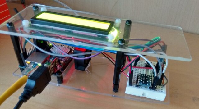
So here it is, my geeky brothers and sisters... in all it's "magnificent splendor" - The Beast (TM):

The Beast (TM) - 4-core ARM, PI(D)-controlled FAN, I2C 1602, level-shifter, and more!
First, make it work
The 'heart' of the contraption is an Orange PI zero board, carrying an H2+ SoC - which is a 4-core ARM Cortex A7. The SoC has Ethernet and USB ports - and can run the 4 cores from 240MHz up to 1.2GHz. It also carries 512MB of RAM - all this for around 12Euros...
SW-wise, I used armbian. To make sure I remained in control of both the HW and the SW, I in fact compiled and created the armbian image myself, based on the excellent Docker-based automation work done by the amazing people behind armbian. I wrote the image I built to a 4GB SD card, and booted to a perfectly-running Debian userland.
Things seemed to work fine, originally - until doing some stress-testing with my renderer. At that point, I witnessed weird instabilities - and after monitoring the voltage levels on the 5V line, I quickly realized that the 5Euro power supply I was using - rated at "5V/3A" - would in fact dip down far below 5V at far less than a 3A draw...
When I used my Raspberry's power supply, all the instabilities disappeared.
So I ordered a 2nd Raspberry PSU - and while waiting, I realized that the SoC's temperature would rise up to 80C during benchmarking! That was quite a difference to my Raspberry PI2's maximum of 58C. At that point, to avoid disasters, armbian would downclock the cores to 240MHz... and performance suffered.
I've never played with fan control of my own making. Good! (rubs hands :-)
Then, make it cool
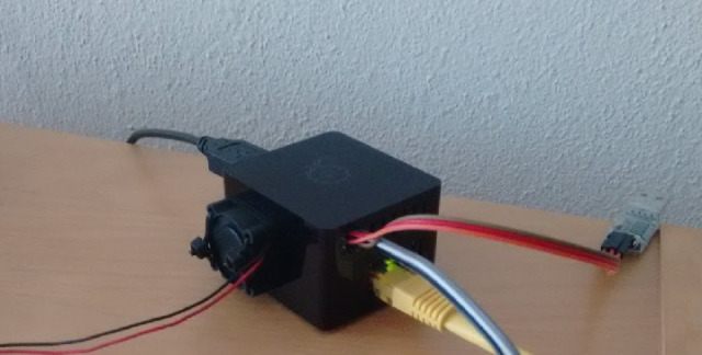
The 5V fan and some dirt-cheap heatsinks arrived in a few days. I drilled a hole in the Orange PI Zero's enclosure, and attached the fan with zip-ties, blowing cool air directly over the Now-with-Heatsink! SoC:

The Beauty - with a serial port PL2303HX for easy getty-access
The fan was powered by the 5V GPIO pin - which is in turn "fed" directly from the USB power jack (the rest of the board runs at 3.3V).
But the result... was not quite what I wanted.
Design a control circuit, Luke
For one, the temperature only dropped by a meagre 10C. The enclosure was simply not designed for this - and the hot air was more or less "trapped" inside it, no matter how hard the tiny fan tried to push it out.
In addition, the end result was also too noisy - the fan was on all the time, and even though it wasn't loud, just like all tiny fans it had a high pitch; the designed-to-drive-you-mad kind.
There was only one way to handle the noise: I needed a control circuit to switch the fan on only when the temperature was high enough. And since the SoC runs at 3.3V, even though the fan had very low current draw, I couldn't just power it - being a 5V fan - directly from the 3.3V GPIO pins...
Which meant it was time to read up on MOSFETs.
I also decided to lose the enclosure, and setup a breadboard next to the SoC. The air flow would be significantly better - with preliminary tests indicating almost an additional 10 degrees worth of difference. With the breadboard close by, I would also be able to hack the control circuitry very easily... not to mention enabling further electronics tinkering in the future.
And how would I keep the whole setup together? Acrylic to the rescue!
Which I've also never worked with before.
Awesome! Let's order some :-)

The fan's control circuit
After a bit of reading on the Internet, I set up the breadboard with an
N-channel MOSFET controlling the fan's connection to ground... and the FET's gate
itself being controlled from a GPIO pin. UPDATE: /u/jms_nh kindly pointed
me to this article which
reminded me to add a current limiting resistor between the GPIO pin and the
gate of the MOSFET.
I then wrote a small Python daemon that read the temperature (via
/sys/class/thermal/thermal_zone0/temp) and appropriately switched
that GPIO pin on/off.
That worked - the noise finally went away, with the fan "waking up" only when necessary.
And soon after, I started reading about PID controllers and created a Supervisor-driven Python daemon that used the SoC's PWM support to control the speed of the fan:
#!/usr/bin/env python2
from __future__ import print_function
import os, sys, time

def printAndFlush(*args, **kwargs):
    print(*args, **kwargs)
    sys.stdout.flush()

#####################
# Parse configuration

CONFIG_FILE = "/etc/fan.conf"
DESIRED = 60
VERBOSE = "-v" in sys.argv

if os.path.exists(CONFIG_FILE):
    for line in open(CONFIG_FILE):
        if line.startswith('#'):
            continue
        try:
            data = line.split("=")
            varname = data[0].strip().lower()
            if varname == "temperature":
                DESIRED = int(data[1].strip())
            elif varname == "verbose":
                VERBOSE = bool(eval(data[1].strip()))
        except:
            pass

def info(*args, **kwargs):
    if VERBOSE:
        printAndFlush(*args, **kwargs)

if os.getenv("TZ") is None:
    os.putenv("TZ", open("/etc/timezone").read().strip())
printAndFlush("[-] Fan daemon started at", time.ctime())
printAndFlush("[-] Target temperature set at", str(DESIRED)+"C.")
printAndFlush("[-] Verbose logging: ", "enabled" if VERBOSE else "disabled")

###########
# Setup PWM

setup_is_needed = False
moduleLines = os.popen("/sbin/lsmod | grep 'p[w]m'").readlines()
if not moduleLines or not moduleLines[0].startswith('pwm_sunxi_opi0'):
    folder = os.path.dirname(os.path.realpath(__file__))
    try:
        os.chdir(folder)
    except OSError:
        printAndFlush("[x] Failed to chdir to folder with PWM module...")
        sys.exit(1)
    info("[-] Loading PWM module... (pwm-sunxi-opi0.ko)")
    if 0 != os.system("/sbin/insmod ./pwm-sunxi-opi0.ko"):
        printAndFlush("[x] Failed to load PWM module... Aborting.")
        sys.exit(1)
    setup_is_needed = True

try:
    PWM = "/sys/class/pwm-sunxi-opi0/pwm0"
    os.chdir(PWM)
except OSError:
    printAndFlush("[x] Failed to chdir to", PWM)
    sys.exit(1)

if setup_is_needed:
    info("[-] Setting up PWM scale from 0 to 100")
    open("run" , "w").write("1")
    open("polarity", "w").write("1")
    open("prescale", "w").write("2")
    open("entirecycles", "w").write("100")

###############
# PI controller

I = 0
while True:
    temp = int(open("/sys/class/thermal/thermal_zone0/temp").read())

    error = temp - DESIRED
    I = I + error
    I = min(I, 100)
    I = max(I, -100)
    PID_target = int(error * 4.0 + I * 0.4)

    if PID_target < 0:
        target = 0
    else:
        target = min(50+PID_target, 100)
    info("[-] Temp is %dC, setting fan at %d%% (I=%s)" % (
        temp, target, str(I)))
    open("activecycles", "w").write(str(target))
    time.sleep(4)
$ cat /etc/fan.conf
# Configuration file for my custom fan daemon

temperature = 65
verbose = 0


$ sudo cat /etc/supervisor/conf.d/fan.conf
[program:fan]
command=/root/bin.local/fan.py
autostart=true
autorestart=true
stderr_logfile=/var/log/fan.stderr.log
stdout_logfile=/var/log/fan.stdout.log


$ sudo supervisorctl start fan

$ sudo tail /var/log/fan.stdout.log
[-] Fan daemon started at Fri Aug  4 11:47:47 2017
[-] Target temperature set at 65C.
[-] Verbose logging:  disabled
The SW parts were easy - Python allows for rapid development. The HW parts of PWM support depended on a kind gentleman's device driver that exposes the OPIZero's PWM functionality (basically, the serial connection's RX pin becomes a PWM pin). I had to re-program the FEX file of the SoC to disable the default serial pins (since the RX one was used for the PWM signal) and configure the serial to use two other GPIO pins.
Yes, I can't live without my UART! Where would I run my getty otherwise!
SSH? Get off my lawn, kid!
(Just kiddin. Sort of :-)
The 1602 screen and the shifter
I played with UARTs, I played with SPI...
Time for I2C!
Not having a screen attached, meant that The Beast was more or less isolated - unless I
ssh-ed or minicom-ed inside it.
I've seen these 1602 LCD screens everywhere, pretty much all my life... but never played with one; this was the perfect opportunity to combine that desire with I2C tinkering.
And in the meantime, the transparent acrylic sheets had arrived - together with the standoffs and the nuts-and-bolts-y things. I failed somewhat at cutting the acrylic properly - it broke at an angle ; but I managed to file it down to something acceptable. I then measured and drilled the holes, trying to make sure I could fit the 1602 screen snugly inside.
The end result:
The I2C parts weren't without their own challenges. The screen was made to work for 5V - I (foolishly!) tried it as-is, and it seemed to work... But after looking around. I realized I was just lucky - my poor PI could have gone up in smoke... (the scope showed that the GPIO pins were pulled up at 3.9V!)
I quickly bought a 1-Euro level shifter from eBay. I've used one before, when I "spoke" to my tablet's hidden serial port - so it was rather easy to setup on my breadboard... and the SDA and SCL levels dropped down to the proper 3.3V.
The rest was simple - I used a nice port of the Wire and Liquid_Crystal
Arduino libraries to control the screen; and output my disk usage, SoC
temperature, CPU load and fan speed.
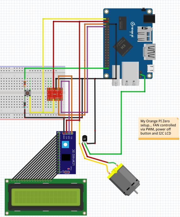
Finally, I added a power-off button - which pulls up a GPIO pin, monitored by another Supervisor-controlled Python daemon, that detects the press and gracefully powers off the device.

NOTE: No Orange PI Zero in Fritzing - this is just an
approximate drawing based on the older Orange PI PC
Besides being my "experimental platform", the Beast also doubles as my file/movie server, and also my Borgbackup server. It is a UNIX server, after all.
3. VHDL and FPGAs
My other - and far more serious excursion into electronics, that I am nowhere near mastering - is that of FPGAs and VHDL coding.
I started by watching the basics of VHDL in 3 videos by Nick Williams. I then worked on a Spartan3 based FPGA, and used the free Xilinx WebPACK to write my own control circuit for a serial port - that I myself exposed from the FPGA as a GPIO pin.
I communicated with my serial port via a PL2303HX adapter, attached to my FPGA's GPIO pins on one side, and to my laptop over USB on the other:
Sending a serial signal was easy - but receiving, that was a different story... The need to sync up to the incoming signal made me deal for the first time with concurrently running VHDL state machines at different clocks.
Lots of fun, debugging this :-) ... since there's no "debugging", really; at least not in the way we do it in SW. Mostly, you simulate your circuit and then look at the signals emitted by it - and compare them to the expected ones in the protocols/datasheets.
And when even that fails, you order a 5 Euro logic analyzer from China... and desperately probe everything. Which, miraculously, worked :-) Many thanks to the excellent people behind Sigrok - they made my cheap analyzer just as efficient as 20 times more expensive products.
This - my FPGA programming attempts - deserves a blog post of its own (for now, I have documented the experience in my repo's README ). This is truly a different world - and somehow, the fact that you express everything as declarations of, basically, pin assignment expressions, meshes in a very interesting way with functional-style thinking and declarative programming.
And since there are open-source CPU designs... I may endeavor to synthesize my own CPU core running inside that FPGA. Which sounds awesome :-)
UPDATE: Done! I ported a Leon3 design from Gaisler's GPL version of the GRLIB, inside my FPGA - and then compiled and executed a program on a CPU that I "compiled" myself :-)
Discussion in Hacker News
Discussion in Hackaday
| Index | CV | Updated: Sat Oct 21 20:37:23 2023 |


